NM-Solar
Overview
The NM-Solar series is a solar energy-storage UPS power-supply board for low-power IoT devices. Model NM-Solar-4.2V/3A accepts USB-C, DC adapter, or 6 V / 18 V solar-panel input with selectable MPPT, charges a 1S lithium-ion battery pack (up to 4.2 V / 3 A), and provides three plug-in output slots (PACK direct / 5 V·3.3 V / 12 V). Main-board standby current is as low as 30 µA.
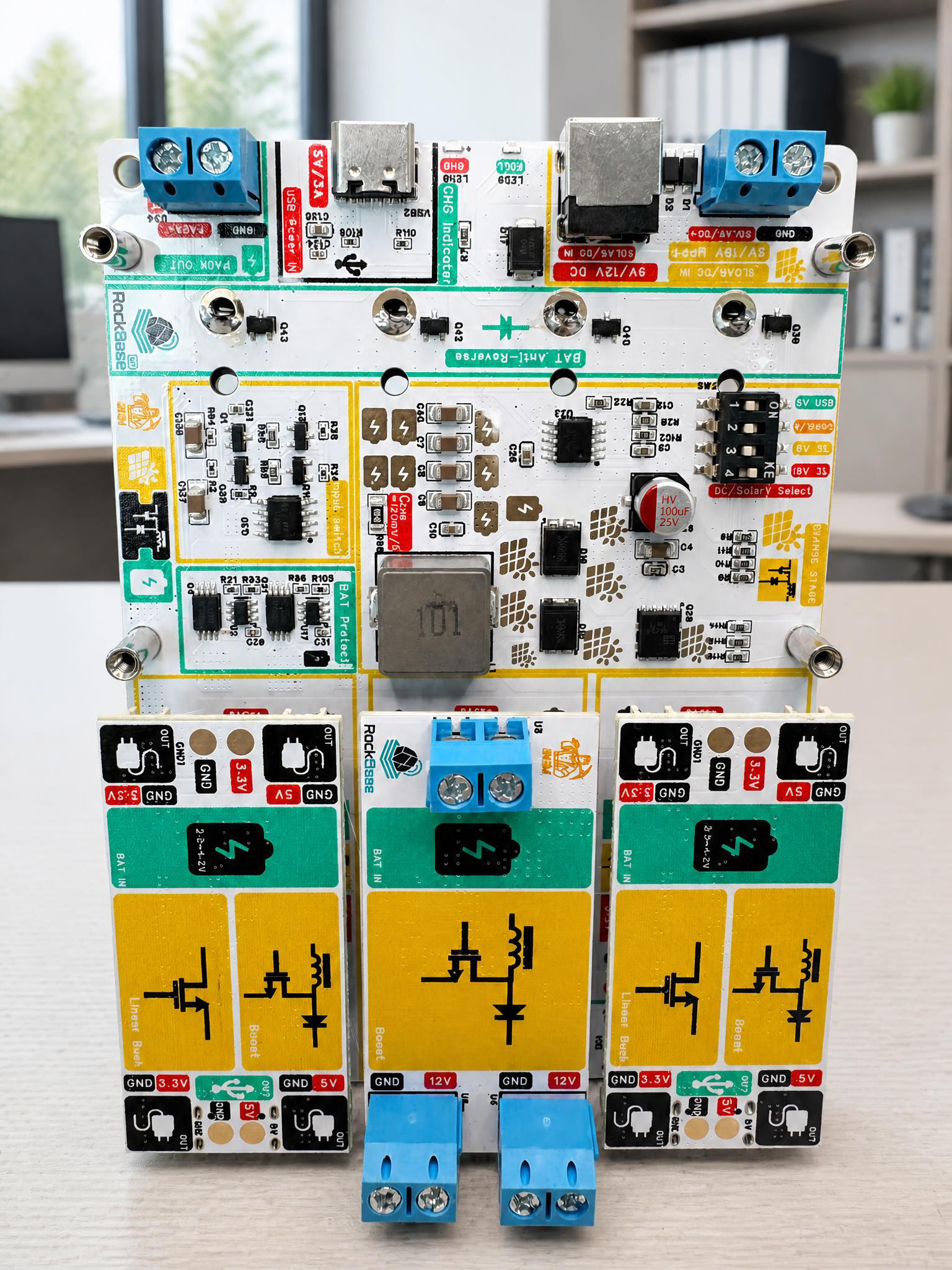
Typical applications include LoRa / Zigbee / Meshtastic / MeshCore nodes, remote sensor terminals, agricultural monitoring equipment, GNSS fixed stations, and short-term UPS backup for home communication or small security devices.
Repository: RockBase-iot/NM-Solar
Key Features
- Three inputs in one: USB-C 5 V, DC adapter (9–12 V), 6 V / 18 V solar panel
- MPPT voltage: selectable 6 V / 18 V solar maximum power point tracking
- Battery balancing: 1–4 parallel 3.7 V 18650 cells with automatic balancing
- Plug-in output modules: three slots supporting PACK direct, 5 V / 3.3 V, and 12 V modules — choose modules to match your needs
- Multiple protections: reverse-polarity, over-charge, over-current, over-voltage, and short-circuit protection
- Ultra-low standby: main-board standby current only 30 µA
- Four-level capacity indication: battery LEDs plus charging / full-charge indicators
General Specifications
| Item | Specification |
|---|---|
| Model | NM-Solar-4.2V/3A |
| USB-C input | 4.5–5.5 V; 13 W maximum input power |
| Input voltage range | 5–25 V |
| Solar input | 6 V or 18 V solar panel |
| DC input | 9 V / 12 V adapter recommended |
| Recommended panel | 10–50 W |
| MPPT selection | 6 V / 18 V selectable |
| Battery | 1S 3.7 V lithium-ion; 1–4 cells in parallel |
| Charge limit | 4.2 V, 3 A maximum |
| Standby current | 30 µA |
| Output slots | Three plug-in slots; 2 × 5-pin, 2.54 mm headers |
| 5 V / 3.3 V module | 5 V / 1 A and 3.3 V / 1 A |
| 12 V module | 12 V / 1 A |
| PACK output | Battery-pack direct output, up to 12 A |
| Combined output limit | 30 W maximum when multiple outputs are used simultaneously |
Charging current depends on the panel and light level. Reference values: a 35 W panel provides approximately 3 A at 150,000 lux and 2.5 A at 130,000 lux; a 20 W panel provides approximately 2 A at 150,000 lux and 1.5 A at 130,000 lux.
Interfaces
Inputs
| Interface | Voltage | Notes |
|---|---|---|
| USB-C | 4.5–5.5 V | Can be connected alongside other inputs; lower priority than DC/solar |
| DC input | 9–12 V recommended | Do not connect a solar panel to the shared input at the same time |
| Solar | 6 V / 18 V | Select the matching MPPT setting before connecting the panel |
Output Slots
| Slot | Output type | Specification |
|---|---|---|
| Slot 1 | PACK direct | Battery-pack voltage direct output, up to 12 A |
| Slot 2 | 5 V / 3.3 V | 5 V / 1 A + 3.3 V / 1 A |
| Slot 3 | 12 V | 12 V / 1 A |
Total output power must not exceed 30 W. Always power off before installing or swapping output modules. Choose output modules that match your actual requirements.
Usage Guide
USB-C Charging
- Connect a stable 5 V USB power source to the USB-C input.
- The CHG (charging) LED lights up.
- The FULL LED lights up when the battery is nearly full.
DC Adapter Charging
- Connect a 9 V or 12 V DC adapter to the DC input.
- Make sure no solar panel is connected to the shared Solar/DC input.
- If USB-C is also connected, the board automatically prioritizes the DC adapter.
Solar Charging
- Select the correct MPPT voltage setting (6 V or 18 V).
- Connect a 6 V or 18 V solar panel with correct polarity.
- Make sure no 9 V / 12 V adapter is connected to the DC input.
Powering Loads
- Confirm the voltage your load requires and select the matching output module.
- Low-power IoT nodes can use the 5 V or 3.3 V output.
- 12 V devices use the 12 V output module.
- Before long-term deployment, verify the load's inrush current is within the module rating.
Quick Start
- Install 1–4 compatible lithium-ion cells with correct polarity.
- Select the input mode (USB-C / DC / solar) before powering on.
- The shared Solar/DC input accepts only one source; USB-C may be connected in addition.
- Install the output module matching your load voltage while powered off.
- Confirm the load power stays within the module rating and the 30 W combined limit.
- Before deployment, check that the charging and capacity indicators behave normally.
Safety Notes
- Never reverse the polarity of inputs, outputs, or the battery.
- Never connect a solar panel and a 9 V / 12 V DC adapter to the shared input at the same time.
- Never exceed the USB-C 13 W input limit, output module ratings, or the 30 W combined output limit.
- Never short the battery pack or output terminals.
- Use intact batteries of identical specifications; do not mix battery chemistries.
- Keep the bare board away from humid, conductive, dusty, or corrosive environments.
Application Scenarios
| Scenario | Description |
|---|---|
| LoRa / Meshtastic nodes | Long-term off-grid mesh nodes powered by solar + battery |
| Agricultural monitoring | Off-grid power for soil-moisture and weather sensors |
| GNSS fixed stations | Stable UPS backup for GPS/GNSS receivers |
| Home IoT gateway | Short-term UPS keeping routers and gateways online |
| Field research | Standalone solar power for low-power data loggers |