Overview
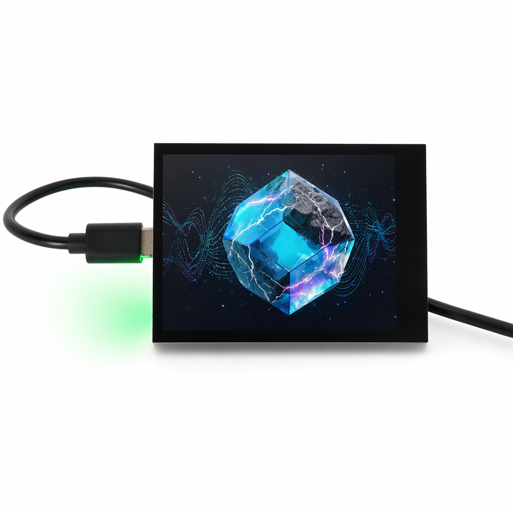
The NM-Display-2.8 is a low-cost IoT display development board based on the ESP32-S3, featuring a 2.8" TFT touchscreen, 6-axis IMU, RTC, audio codec, and power management IC. It is suitable for smart home control panels, IoT Human-Machine Interface (HMI), and edge AI Agent display terminals.
Hardware Specifications
Core Configuration
| Item | Specification |
|---|
| MCU | ESP32-S3 Dual-core Xtensa LX7, 240 MHz |
| SRAM | 512 KB + 8 MB PSRAM |
| Flash | 16 MB SPI Flash |
| Wireless | Wi-Fi 4 (802.11 b/g/n) + Bluetooth 5.0 LE |
| Display | 2.8" ST7789, 320 × 240 pixels |
| Touch | FT6336 capacitive touch (I2C) |
| Resolution | 320 × RGB × 240 |
| Interface | USB Type-C (power / programming) |
Onboard Resources
| Device | Model | Bus |
|---|
| IMU | QMI8658 (6-axis accelerometer / gyroscope) | I2C |
| RTC | PCF85063 (real-time clock) | I2C |
| Audio Codec | ES8311 (I2S) | I2C control + I2S data |
| PMU | AXP2101 | I2C |
| IO Expander | TCA9554 | I2C |
| Camera | OV series DVP interface (optional) | DVP |
| SD Card | SDMMC 1-bit mode | SDMMC |
| Backlight | LEDC PWM dimming | GPIO |
Pinout
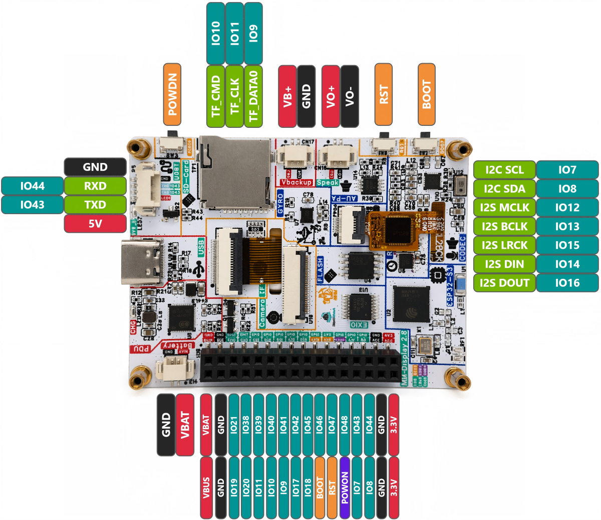
Power & Debug
| GPIO | Function | Description |
|---|
| GND | Ground | Ground |
| 3V3 | 3.3V Output | External 3.3V output (max 500 mA) |
| TXD | UART TX (GPIO43) | Serial TX / general GPIO |
| RXD | UART RX (GPIO44) | Serial RX / general GPIO |
I2C Bus (Shared)
| GPIO | Function | Description |
|---|
| IO7 | I2C SCL | Common I2C clock (not available as regular GPIO) |
| IO8 | I2C SDA | Common I2C data (not available as regular GPIO) |
All of the following peripherals share a single I2C bus (I2C_NUM_0): TCA9554, FT6336, AXP2101, ES8311 (control), QMI8658, PCF85063.
Display (ST7789)
| GPIO | Function |
|---|
| IO1 | SPI MOSI |
| IO5 | SPI SCLK |
| IO3 | LCD DC |
| IO6 | Backlight BL (PWM) |
| NC | SPI CS |
| NC | LCD RESET |
- Interface: SPI, clock 80 MHz, SPI Mode 3
- Driver: ST7789
- Resolution: 320×240 (logical width×height at 270° rotation)
Touch Screen (FT6336, I2C)
| GPIO | Function | Description |
|---|
| IO7 | I2C SCL | Touch controller clock |
| IO8 | I2C SDA | Touch controller data |
| NC | TP INT | Touch interrupt (not connected) |
| NC | TP RESET | Touch reset (not connected) |
Audio Codec (ES8311)
| GPIO | Function | Description |
|---|
| IO7 | I2C SCL | ES8311 control bus |
| IO8 | I2C SDA | ES8311 control data |
| IO12 | I2S MCLK | I2S master clock |
| IO13 | I2S BCLK | I2S bit clock |
| IO15 | I2S LRCK | I2S left / right clock |
| IO14 | I2S DIN | Recording data input |
| IO16 | I2S DOUT | Playback data output |
Camera (DVP Interface)
| GPIO | Function | Description |
|---|
| IO38 | XCLK | Camera clock output |
| IO17 | VSYNC | Vertical sync signal |
| IO18 | HREF | Horizontal reference signal |
| IO41 | PCLK | Pixel clock |
| IO45 | D0 (Y2) | Data bit 0 |
| IO47 | D1 (Y3) | Data bit 1 |
| IO48 | D2 (Y4) | Data bit 2 |
| IO46 | D3 (Y5) | Data bit 3 |
| IO42 | D4 (Y6) | Data bit 4 |
| IO40 | D5 (Y7) | Data bit 5 |
| IO39 | D6 (Y8) | Data bit 6 |
| IO21 | D7 (Y9) | Data bit 7 |
| IO8 | SCCB SDA | (shared I2C bus) |
| IO7 | SCCB SCL | (shared I2C bus) |
- XCLK frequency: 20 MHz
- Frame format: RGB565, 320×480
SD Card (SDMMC 1-bit)
| GPIO | Function | Description |
|---|
| IO9 | SDMMC D0 | Data bit 0 |
| IO10 | SDMMC CMD | Command line |
| IO11 | SDMMC CLK | Clock line |
- Mount point:
/sdcard
- Mode: 1-bit SDMMC
| GPIO | Function | Description |
|---|
| IO0 | BOOT Button | Boot button (active low) |
Others
| GPIO | Function | Description |
|---|
| IO1 | Debug TX | Debug serial TX |
| IO2 | Debug RX | Debug serial RX |
| IO3 | Touch INT / GPIO | Touch interrupt or general GPIO |
| IO4 | Battery ADC | Battery voltage detection (optional) |
Quick Start
1. Hardware Preparation
| Item | Quantity |
|---|
| NM-Display-2.8 board | ×1 |
| USB-C cable | ×1 |
| (Optional) Battery (3.7V LiPo) | ×1 |
2. Development Environment Setup
Recommended: ESP-IDF v5.3+.
bash -c "$(curl -fsSL https://espressif.github.io/esp-idf/install.sh)"
source ~/esp-idf/export.sh
git clone https://github.com/RockBase-iot/NM-Display-28inch.git
cd NM-Display-28inch
idf.py set-target esp32s3
idf.py menuconfig
idf.py build
idf.py flash monitor
3. First Flash
esptool.py --chip esp32s3 --port /dev/ttyUSB0 write_flash 0x1000 bootloader.bin 0x8000 partition-table.bin 0x10000 app.bin
4. Serial Monitor
Onboard Peripheral Drivers
IMU Driver (QMI8658)
#include "qmi8658.h"
i2c_dev_t qmi8658;
esp_err_t ret = qmi8658_init(&qmi8658, I2C_NUM_0);
qmi8658_val mag;
ret = qmi8658_read_mag(&qmi8658, &mag);
RTC Driver (PCF85063)
#include "pcf85063.h"

pcf85063_set_time(&i2c_dev, 2026, 5, 19, 16, 56, 0);
pcf85063_get_time(&i2c_dev, &datetime);
Audio Playback (ES8311)
#include "es8311.h"
es8311_init(I2C_NUM_0);
es8311_set_volume(80);
es8311_play(audio_buffer, length);
Touch Screen (FT6336)
#include "ft6336.h"

ft6336_init(I2C_NUM_0);
touch_point_t point;
if (ft6336_read_touch(&point)) {
    printf("Touch: x=%d, y=%d\n", point.x, point.y);
}
FAQ
Q1: What if the touch screen has no response?
A1: Check if IO7/IO8 are occupied by other devices. I2C address conflicts can cause touch failure. Use the i2cdetect tool to scan the I2C bus and verify the touch chip address is 0x38 or 0x48.
Q2: How to troubleshoot backlight issues?
A2: Backlight is controlled by IO21 (LEDC PWM). Verify GPIO21 is correctly configured. Measure the backlight voltage on the LCD board to confirm the circuit is functioning.
Q3: SD card fails to mount?
A3: Ensure SDMMC pins (IO9/IO10/IO11) are not occupied by other functions. Check if the SD card is formatted as FAT32, maximum supported capacity is 32GB.
Q4: How to enter download mode?
A4: Hold the BOOT button, press and release the RST button, then release the BOOT button. The device will enter UART download mode.
Q5: What if the device fails to boot after a sudden power loss?
A5: It may be caused by the PMU protection being triggered due to low input voltage from the USB port. Try replacing with a high-quality power supply or using battery power. In addition, for applications using peripherals such as the camera, make sure to check that the PMU AXP2101 is configured correctly to ensure the power management IC can provide sufficient current. Refer to the NM-Display-2.8 Factory Test Code for details.
Reference Resources